


Longer Nano Duo
Engrave Like a Master
About Us
With Longer, Make It better


Blobs in 3D Printing

Many users of 3D printing, regardless of their experience, often find themselves facing an annoying problem that is really difficult to eliminate: blobs on the outer surface of the prints. This phenomenon often appears suddenly, only on particular prints, even when you think you have found the perfect Slicer settings for optimal print quality. So we proceed with varying the temperature, the speed, the accelerations, etc., but despite this the problem is not solved, but only a little attenuated.
Blobs are deposits of molten material along the outer surface of a print, take on the appearance of "little balls" and are difficult to remove even by handworking the print in post-production. These occur when the nozzle abnormally releases molten material, and often this is independent of slicer settings such as retraction and flow.

When math is indispensable for 3D printing
In geometry, a polygon takes on a different name and appearance based on its number of sides (segments). In particular, a polygon composed of 3 segments will be called a triangle, composed of 5 segments will be called pentagon, 6 hexagon segments, 10 decagon segments, ..........., from 1.000.000.000 segments will be something very similar to a circumference, from 1.000.000.000.000 segments will look almost a circumference, from 1.000.000.000.000.000.000 segments will be practically a circumference.
Thus, a polygon of n-sides, with very large n and each segment very small, can be approximated with a circle, with greater precision as nincreases. This technique is used by 3D printers to print a circumference, transforming it into a series of XY coordinates of n segments, with n more or less large depending on the number of meshes of the original stl model. Thus, a circumference is a series of countless segments, each of very small amplitude, made one after another on the hotbed of the 3D printer.
However, what to the eye seems to be a very simple circumference, actually requires a high computational cost for the mainboard of the 3D printer, as it is necessary to process in a fraction of a second millions of coordinates of millions of segments. In addition, depending on the number of meshes of the original stl model, 3D printing may often have to process much more data than is sufficient to achieve a perfect circumference, sometimes even more than its hardware capacity in terms of resolution.
Therefore, if for example the 3D printer can realize a perfect circumference starting from 10.000.000.000 segments, and this is also its maximum resolution, when its mainboard is found to process 1.000.000.000.000.000 segments this will perform unnecessary work, both because it is possible to obtain an optimal result with a lower computational cost and because such processing cannot be put into practice due to the hardware limitations of an FDM printer.
Correlation between geometry and blobs
As seen above, for a simple circumference, a 3D printer is faced with a very complex calculation in no time, often a calculation even greater than necessary. So it can happen that the mainboard cannot process the data in time, so the hardware not receiving print coordinates can only stop. These stops occur for a very short time, almost imperceptible, but they are enough for the nozzle to lose molten material along the outer perimeter of printing, thus forming a blob.
Therefore, regardless of one's slicing settings, the blobs phenomenon cannot be solved easily as it is dependent on the type of 3D drawing, its number of meshes, the original designer's ability to make it, and the computational ability of the mainboard of your 3D printer.
Resolve the problem
The optimal approach to solve this problem would be to manipulate the stl file in question, going to reduce the number of meshes, repair it and try to reduce its size in terms of megabytes. However, this operation often turns out to be complex, suitable only for experts, or even impossible.
On the other hand, the Ultimaker Care slicer is equipped with a special, hidden feature that not everyone knows about, which is very useful for reducing the number of meshes of a 3D object. This option is called "Mesh Fixes" and is intended to reduce the number of meshes of an object by varying the maximum length of each segment. In this way, by increasing the maximum distance of each segment, at the same perimeter inevitably the number of segments must be smaller, and therefore the computational cost of the mainboard is also reduced. Therefore, by processing the gcode more easily, the 3D printer will be able to process a greater number of displacements without suffering from pauses, and therefore reducing the blobs.
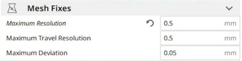
In particular, by changing the default settings with the values above it will be possible to solve almost entirely the problem of blobs, without altering the standard FDM print quality. It should be considered in mind that professional 3D printers, such as FDM Ultimaker printers, adopt by default values of 0.7 mm without affecting their ability to make details and resolution.
If after changing the parameters in question should still persist some sporadic blobs, it will be possible to totally solve the problem by slightly adjusting the values of temperature and downward flow, the upward retraction. Alternatively, you can always increment the Mesh Fixes values at the expense of details.
The print difference with the standard and custom Mesh Fixes settings are immediately visible:
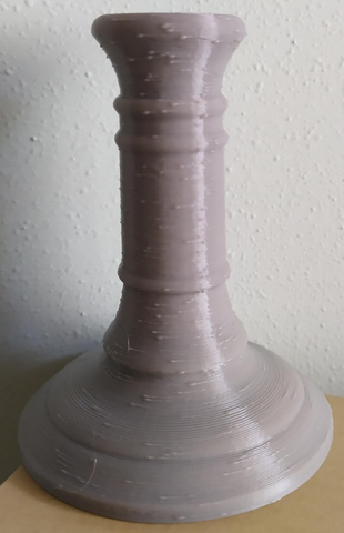
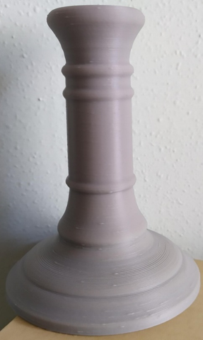
Both tests were done keeping the exact same slicing settings for both, except for varying the Mesh Fixes values.
The test stl file has been modified, damaged and repaired three times, in order to make it difficult for the mainboard to be processed.
https://www.longer3d.com/products/lk5-pro-fdm-3d-printer
- Choosing a selection results in a full page refresh.
Products
Support
Policy
Follow Us
Contact Us
!